Sunday, July 31, 2011

8WATT LED DRIVER SOLUTIION


Specifications
Item Name: LED DRIVER
Input: 90 to 300 VAC ; 47 - 53 Hz, L N E
Output: WITH POWER FACTOR CORRECTION
16V@0.7A
Power factor & THD: 0.99 & 8-16%
Line and Load Regulation:1 %
Output Ripple: 1 %,
Operating Temperature:-10 to 50 deg C ; RH 95 % non condensing
Output Isolation: 1.5 KV rms @ 50 Hz for 1 minute.
Other Features: • Output over voltage protection • Input EMI-RFI filters
• Output LED indication • Integrated MOSFET and PFcontrollers
for greater reliability and space saving
Efficiency:>85 % at full load and normal I/P
Stand by power:<100mW
Output variation: Apprx. ±1%

IF U WOULD LIKE TO DESIGN THIS PRODUCT THAN CALL ME :9716933131
OR MAIL ME:kaushal.talk@gmail.com

25 WATT LED DRIVER SOLUTION


Specifications
Item Name: LED DRIVER
Input: 90 to 300 VAC ; 47 - 53 Hz, L N E
Output: WITH POWER FACTOR CORRECTION
90V@0.35A
Power factor & THD: 0.99 & 8-16%
Line and Load Regulation:1 %
Output Ripple: 1 %,
Operating Temperature:-10 to 50 deg C ; RH 95 % non condensing
Output Isolation: 1.5 KV rms @ 50 Hz for 1 minute.
Other Features: • Output over voltage protection • Input EMI-RFI filters
• Output LED indication • Integrated MOSFET and PFcontrollers
for greater reliability and space saving
Efficiency:>85 % at full load and normal I/P
Stand by power:<100mW
Output variation: Apprx. ±1%

IF U WOULD LIKE TO DESIGN THIS PRODUCT THAN CALL ME :9716933131
OR MAIL ME:kaushal.talk@gmail.com

20 WATT LED DRIVER SOLUTION


Specifications
Item Name: 20 WATT LED DRIVER
Input: 90 to 300 VAC ; 47 - 53 Hz, L N E
Output: WITH POWER FACTOR CORRECTION
40V@0.7A
Power factor & THD: 0.99 & 8-16%
Line and Load Regulation:1 %
Output Ripple: 1 %,
Operating Temperature:-10 to 50 deg C ; RH 95 % non condensing
Output Isolation: 1.5 KV rms @ 50 Hz for 1 minute.
Other Features: • Output over voltage protection • Input EMI-RFI filters
• Output LED indication • Integrated MOSFET and PFcontrollers
for greater reliability and space saving
Efficiency:>85 % at full load and normal I/P
Stand by power:<100mW
Output variation: Apprx. ±1%

IF U WOULD LIKE TO DESIGN THIS PRODUCT THAN CALL ME :9716933131
OR MAIL ME:kaushal.talk@gmail.com

35WATT LED DRIVER SOLUTION


Specifications
Item Name:SMPS 54V @ 0.7A
Input:90 to 300 VAC ; 47 - 53 Hz, L N E
Output:54 V @ 0.7 A WITH POWER FACTOR CORRECTION
Power factor & THD:0.9999 & 8-16%
Line and Load Regulation:1 %
Output Ripple:1 %,
Operating Temperature:-10 to 50 deg C ; RH 95 % non condensing
Output Isolation: 1.5 KV rms @ 50 Hz for 1 minute.
Other Features: • Output over voltage protection • Output short circuit protection
• Input EMI-RFI filters • Screw type input / output connectors • Output LED indication
• Integrated MOSFET and PWM controllers for greater reliability and space saving.
Efficiency:>85 % at full load and normal I/P
Stand by power:<100mW
Output variation:Apprx. ±1%

IF U WOULD LIKE TO DESIGN THIS PRODUCT THAN CALL ME :9716933131
OR MAIL ME:kaushal.talk@gmail.com

Saturday, July 30, 2011

65 WATT LED DRIVER SOLUTION


Specifications
Item Name: SMPS 85V @ 0.7A
Input: 90 to 300 VAC ; 47 - 53 Hz, L N E
Output: 85 V @ 0.7 A WITH POWER FACTOR CORRECTION
Power factor & THD: >0.95 & 8-12%
Line and Load Regulation: 1 %
Output Ripple: 1 %,
Operating Temperature:-10 to 50 deg C ; RH 95 % non condensing
Output Isolation: 1.5 KV rms @ 50 Hz for 1 minute.
Other Features: • Output over voltage protection • Output short circuit protection
• Input EMI-RFI filters • Screw type input / output connectors • Output LED indication
• Integrated MOSFET and PWM controllers for greater reliability and space saving Option for PWM dimming the LED
Efficiency: >85 % at full load and normal I/P
Output current variation: Approx. ±5%

IF U WOULD LIKE TO DESIGN THIS PRODUCT THAN CALL ME :9716933131
OR MAIL ME:kaushal.talk@gmail.com

Sunday, July 24, 2011

SMPS 5V@5A 25 watt solution:

 Specification’s
of
SMPS 5V @ 5A

you can manufacture, switched-mode power supply
(SMPS) (SMPS 5V @ 5A) is an electronic power
supply unit (PSU) that incorporates a switching
=>regulator. The salient features are enlisted below:
=>Input: 170 to 300 VAC ; 47 - 53 Hz, 3 wire
=>Output: 5 V @ 5 A
=>Line and Load Regulation: 1 %
=>Output Ripple: 1 %,
=>Operating Temperature: -10 to 50 deg C ; RH 95 % non condensing
=>Output Isolation: 1.5 KV rms @ 50 Hz for 1 minute.
=>Other Features: Input over voltage latch protection • Output over
voltage latch protection • Over temperature protection
• Output short circuit protection • Input EMI-RFI
filters • Screw type input / output connectors • Output
LED indication • Integrated MOSFET and PWM
controllers for greater reliability and space saving
=>Efficiency: >77 % at full load and normal I/P
=>Stand by power: <0.2W
=>Output variation: Approx. ±5% through preset.

25 watt power supply schematic :
I will make easy for u: 
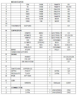
list of material :1

list of material:2
transformer design: for 5volt @5amp.
Testing procedure
for
5volt @5amp.
1. Turn the output voltage adjustment preset to maximum. Connect to
normal input voltage and turn on the SMPS to check if it shuts down.
It should not shut down.
2. Adjust preset for rated output voltage.
3. Load the SMPS for rated full load.
4. Vary the AC input supply by variac from 170 to 300VAC and note if
there is any major change in output voltage.
5. Increase input voltage greater than 300VAC to check line overvoltage
shutdown.
6. Measure Drain voltage of device. At 420VDC input it should be a
maximum of 630V.
7. Check the input voltage at which the SMPS shuts down and gets
latched (input over voltage latching shutdown). It should be less than
440 volts.
8. Check the output voltage at which the SMPS shuts down and gets
latched (output over voltage latching shutdown). It should be greater
than the maximum adjustment limit of output adjustment preset.
9. Perform a High-voltage test of 1.5KV for 1 minute –
a. Between Input and Output.
b. Between Input and Earth.
PCB layout guideline

thanks 
kaushalesh singh(9716933131)

Thursday, July 14, 2011

12 WATT SMPS SOLUTION

Specifications
Of
Item Name:     SMPS 12V @ 1A
Item Code:  09A
switched-mode power supply (SMPS) (SMPS 12V @ 1A) is an electronic power supply unit (PSU) that incorporates a switching regulator. The salient features are enlisted below:

Input:     170 to 265 VAC ; 47 - 53 Hz, L N 

Output:     12V @ 1A
Line and Load Regulation:    1 %
Output Ripple:  1%,
Operating Temperature:    -10 to 50 deg C ; RH 95 % non condensing
Output Isolation:    1.5 KV rms @ 50 Hz for 1 minute.
Other Features:    
Output short circuit protection • Input EMI-RFI filters • Screw type input / output connectors • Output LED indication • Integrated MOSFET and PWM controllers for greater reliability and space saving

Efficiency:  >74 % at full load and normal I/P
Stand by power: <1.12
Output variation: Apprx. ±5% through preset.
SCHEMATIC FOR 12V 1A


COMPONENT  DETAIL


TRANSFORMER DETAIL'S


PCB DRAWING
     TESTING PROCEDURE:

      RATING:  I/P:170V~265VAC,  O/P: 12V--1A       
      A) VISUAL CHECKING

     CHECK DRY SOLDERING  CHECK POLARITY OF COMPONENT.
      B) ELECTRICAL TEST

1. Connect the input and output, make sure the Line Neutral Earth at CN1 is OK and +Ve, -Ve at output is proper on your zic without Load and adjust the variac for 170V.

2.  Switch on the psu and see the operation  as follows:

            (a). Bulb in series with a little glow. 

            (b). Output voltmeter show voltage 12V ±1%.

            (c). If the AC ampere meter is on your zic, check the current in mA is showing.

            (d). Output  LED indication is Green.

3. Bypass the bulb and increase the load gradually to the maximum (1A) [make sure that your load resistance is proper] see the voltage regulation is ok (±1% is recommended) and increase  the input voltage up to 265Vac and confirm that line regulation is maintaining [±1% recommended ].                                                                                             

4. Switch ON and OFF the power supply many times with full load, both at low ac input [170V] and high ac input[265V]. make sure every time working properly.

5.Increase the Ac volt up to 280v and see the shutdown in between 280v and 290v and Decrease the voltage 265V and see restarting.